2.3 Mathematical description of internal forces in solids
Our next objective is to outline the
mathematical formulas that describe internal and external forces acting on a
solid. Just as there are many different
strain measures, there are several different definitions of internal
force. We shall see that internal forces
can be described as a second order tensor, which must be symmetric. Thus, internal forces can always be
quantified by a set of six numbers, and the various different definitions are
all equivalent.
2.3.1 Surface traction and internal body force
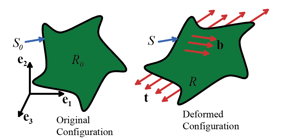 Forces can be applied to a solid body
in two ways, as illustrated in the figure
Forces can be applied to a solid body
in two ways, as illustrated in the figure
1. A force can be applied to its
boundary: examples include fluid pressure, wind loading, or forces arising from
contact with another solid.
2. The solid can be subjected to body forces, which act on the interior
of the solid. Examples include
gravitational loading, or electromagnetic forces.
These forces are quantified using the
surface traction vector, and the body force vector, respectively. These are defined as follows:
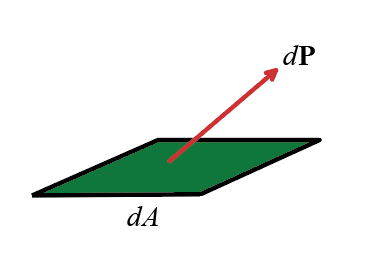
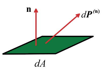
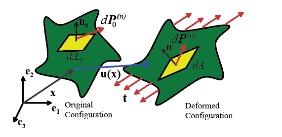
The surface traction vector t at a point on the surface represents
the force acting on the surface per unit area of the deformed solid. Formally, let dA be an element of area on a surface. Suppose that dA is subjected to a force , as shown in the figure. Then
The resultant force acting on any portion S of the surface of the deformed solid
is
Surface traction, like `true stress,’
should be thought of as acting on the deformed solid.
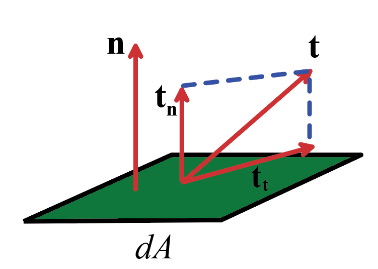 The traction vector
is often resolved into which are components
acting normal and tangential to a surface, as shown in the figure. The normal
component is referred to as the normal
traction, and the tangential component is known as the shear traction.
The traction vector
is often resolved into which are components
acting normal and tangential to a surface, as shown in the figure. The normal
component is referred to as the normal
traction, and the tangential component is known as the shear traction.
Formally, let n denote a unit vector normal to the surface. Then
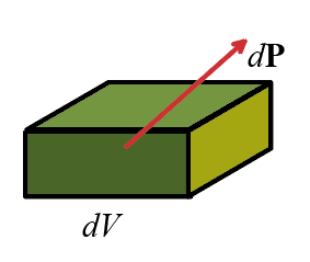 The body force vector denotes
the external force acting on the interior of a solid, per unit mass. Formally, let dV
denote an infinitesimal volume element within the deformed solid, and let denote the mass density (mass per unit
deformed volume). Suppose that the
element is subjected to a force , as shown in the figure. Then
The body force vector denotes
the external force acting on the interior of a solid, per unit mass. Formally, let dV
denote an infinitesimal volume element within the deformed solid, and let denote the mass density (mass per unit
deformed volume). Suppose that the
element is subjected to a force , as shown in the figure. Then
The resultant body force acting on
any volume V within the deformed solid is
 2.3.2 Traction acting on planes
within a solid
2.3.2 Traction acting on planes
within a solid
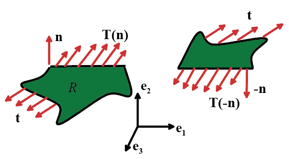
Every plane in the interior of a
solid is subjected to a distribution of traction. To see this, consider a loaded, solid, body
in static equilibrium. Imagine cutting
the solid in two, as illustrated in the figure. The two parts of the solid must
each be in static equilibrium. This is
possible only if forces act on the planes that were created by the cut. We quantify these forces by means of the internal
traction vector T(n), which represents the force per unit area acting on an
internal plane of a solid. The notation T(n)
shows that the internal traction depends on the normal to the internal
plane, denoted by n.
 Formally, let dA be an element of area in the interior of the solid, with normal n.
Suppose that the material on the underside of dA is subjected to a force across the plane dA, as shown in the figure. Then
Formally, let dA be an element of area in the interior of the solid, with normal n.
Suppose that the material on the underside of dA is subjected to a force across the plane dA, as shown in the figure. Then
Note that internal traction is the force per unit area of the deformed solid, like `true stress.’ The traction vector has the following
properties
· The resultant force acting on any internal volume V
with boundary surface A within
a deformed solid is
The first term is the resultant force
acting on the internal surface A, the
second term is the resultant body force acting on the interior V.
· 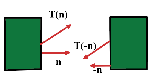 Newton’s third law (every action has an equal and
opposite reaction) requires that
Newton’s third law (every action has an equal and
opposite reaction) requires that
To see this, note that the forces
acting on planes separating two adjacent volume elements in a solid must be
equal and opposite, as shown in the figure.
· Traction acting on different planes passing through the
same point are related, in order to satisfy Newton’s second law (F=ma). Specifically, let be a Cartesian basis. Let , , denote the components of traction acting on
planes with normal vectors in the , , and directions, respectively. Then, the traction components acting on a surface with normal n are given by
where are the components of n.
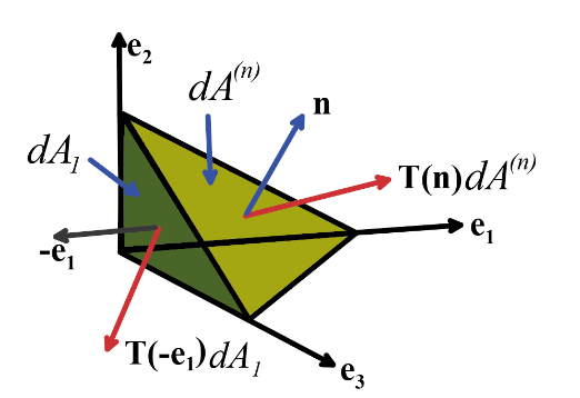
To see this,
consider the forces acting on the infinitessimal tetrahedron shown in the
figure. The base and sides of the
tetrahedron have normals in the , and directions.
The fourth face has normal n. Suppose the volume of the tetrahedron is dV, and let , , , denote the areas of the faces. Assume that the material within the
tetrahedron has mass density and is subjected to a body force b. Let a denote the acceleration of the center of mass of the tetrahedron.
Then, F=ma for the tetrahedron requires that
Recall
that and divide through by :
Finally,
let . We can show (see Appendix E) that
So
or, using index
notation
The significance of this result is
that the tractions acting on planes with normals in the , , and directions completely characterize the
internal forces that act at a point.
Given these tractions, we can deduce the tractions acting on any other
plane. This leads directly to the
definition of the Cauchy stress tensor in the next section.
2.3.3 The Cauchy (true) stress tensor
Consider a solid which deforms under
external loading. Let be a Cartesian basis. Let , , denote the components of traction acting on
planes with normals in the , , and directions, respectively, as outlined in the
preceding section.
Define the components of the Cauchy
stress tensor by
Then, the traction acting on any plane with normal n follows as
To see this, recall the last result
from the preceding section
and substitute for in terms of the components of the Cauchy
stress tensor
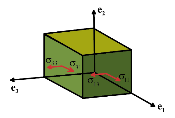
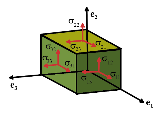 The Cauchy stress tensor completely
characterizes the internal forces acting in a deformed solid. The physical significance of the components
of the stress tensor is illustrated in the figure. represents the ith component of traction acting on a plane with normal in the direction.
The Cauchy stress tensor completely
characterizes the internal forces acting in a deformed solid. The physical significance of the components
of the stress tensor is illustrated in the figure. represents the ith component of traction acting on a plane with normal in the direction.
Note that Cauchy stress represents force per
unit area of the deformed solid. In elementary strength of materials courses
it is called `true stress,’ for this reason.
HEALTH WARNING: Some texts define stress as the transpose of the definition used here,
so that .
In this case the first index for each stress component denotes the
direction of traction, while the second denotes the normal to the plane. We will see later that Cauchy stress is
always symmetric, so there is no confusion if you use the wrong definition. But some stress measures are not symmetric (see below) and in this
case you need to be careful to check which convention the author has chosen.
2.3.4 Other
stress measures Kirchhoff, Nominal and Material
stress tensors
Cauchy stress (the actual force per unit area acting on an
actual, deformed solid) is the most physical measure of internal force. Other definitions of stress often appear in
constitutive equations, however.
The other stress measures regard
forces as acting on the undeformed
solid. Consequently, to define them we
must know not only what the deformed solid looks like, but also what it looked
like before deformation. The deformation
is described by a displacement vector and the associated deformation gradient
as outlined in Section 2.2. In
addition, let .
We then define the following stress
measures
· Kirchhoff stress
· Nominal (First Piola-Kirchhoff) stress
· Material (Second Piola-Kirchhoff) stress
The inverse relations are also useful
the one for Kirchhoff stress is obvious the others are
The Kirchhoff stress has no obvious physical significance, but the
quantity (where D
is the stretch rate tensor) represents the rate of work done by stress per unit
undeformed volume, which is why the Kirchhoff stress is useful.
The nominal stress
tensor can be regarded as the internal force per unit undeformed area
acting within a solid, as follows
1. Visualize an element of area dA in the deformed solid, with normal n, which is subjected to a force by the internal traction in the solid;
2. Suppose that the element of area dA has started out as an element of area with normal in the undeformed solid, as shown in the
figure.
3. Then, the force is related to the nominal stress by
To see this, note that one can show (see Appendix E) that
Recall that the
Cauchy stress is defined so that
Substituting for and rearranging shows that
The material stress tensor can also be visualized as force per unit
undeformed area, except that the forces are regarded as acting within the
undeformed solid, rather than on the deformed solid. Specifically
1. The infinitesimal
force is assumed to behave like an infinitesimal
material fiber in the solid, in the sense that it is stretched and rotated just
like an small vector dx in the solid;
2. This means that we can define a (fictitious) force in the
reference configuration that is related to by or ;
3. This fictitious force is related to material stress by .
To see this, substitute into the
expression relating to nominal stress to see that
Finally multiply through by , note , and rearrange to see that
where we have noted that
In practice, it is best not to try to
attach too much physical significance to these stress measures. Cauchy stress is the best physical measure of
internal force it is the force per unit area acting inside
the deformed solid. The other stress
measures are best regarded as generalized
forces (in the sense of Lagrangian mechanics), which are work-conjugate to
particular strain measures. This means
that the stress measure multiplied by the time derivative of the strain measure
tells you the rate of work done by the forces.
When setting up any mechanics problem, we always work with conjugate
measures of motion and forces.
Specifically, we shall show later
that the rate of work done by stresses acting on a small material
element with volume in the undeformed solid (and volume in the deformed solid) can be computed as
where is the stretch rate tensor, is the rate of change of deformation gradient,
and is the rate of change of Lagrange strain
tensor. Note that Cauchy stress (and
also Kirchhoff stress) is not conjugate to any convenient strain measure this is the main reason that nominal and
material stresses need to be defined.
The nominal stress is conjugate to the deformation gradient, while the
material stress is conjugate to the Lagrange strain tensor.
2.3.5
Stress measures for infinitesimal deformations
For a problem involving infinitesimal deformation (where shape
changes are characterized by the infinitesimal strain tensor and rotation
tensor) all the stress measures defined in the preceding section are approximately
equal
To see this, write the deformation
gradient as ; recall that , and finally assume that for
infinitesimal motions .
Substituting into the formulas relating Cauchy stress, Nominal stress
and Material stress, we see that
The same procedure will show that
material stress and Cauchy stress are approximately equal, to within a term of
order
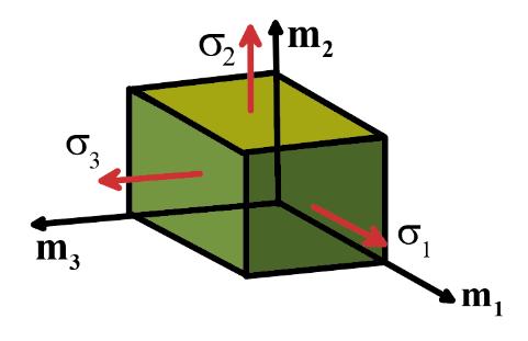
2.3.6 Principal Stresses and directions
For any stress measure, the principal stresses and their directions , with i=1..3 are defined such that
Clearly,
- The principal stresses are the left
eigenvalues of the stress tensor
- The principal stress directions are
the left eigenvectors of the stress tensor
 The term `left’ eigenvector and
eigenvalue indicates that the vector multiplies the tensor on the left. We will
see later that Cauchy stress and material stress are both symmetric. For a symmetric tensor the left and right
eigenvalues and vectors are the same.
The term `left’ eigenvector and
eigenvalue indicates that the vector multiplies the tensor on the left. We will
see later that Cauchy stress and material stress are both symmetric. For a symmetric tensor the left and right
eigenvalues and vectors are the same.
Note that the eigenvectors of a
symmetric tensor are orthogonal.
Consequently, the principal Cauchy or material stresses can be
visualized as tractions acting normal to the faces of a cube, as show in the
figure. The principal directions specify the orientation of this special cube.
One can also show
that if , then is the largest normal traction acting on any
plane passing through the point of interest, while is the lowest.
This is helpful in defining damage criteria for brittle materials, which
fail when the stress acting normal to a material plane reaches a critical
magnitude.
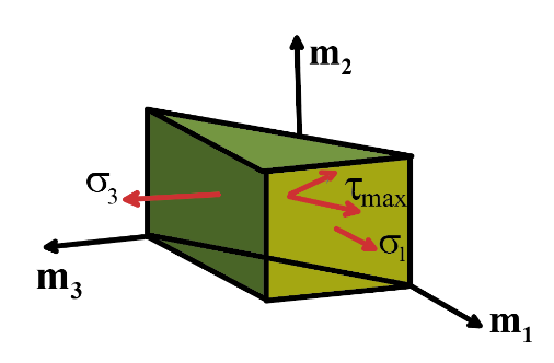 In the same vein, it can be shown
that the largest shear stress acts on the plane with unit normal vector (at 45o to the and axes as shown in the figure, and has magnitude
.
This observation is useful for defining yield criteria for metal
polycrystals, which begin to deform plastically when the shear stress acting on
a material plane reaches a critical value.
In the same vein, it can be shown
that the largest shear stress acts on the plane with unit normal vector (at 45o to the and axes as shown in the figure, and has magnitude
.
This observation is useful for defining yield criteria for metal
polycrystals, which begin to deform plastically when the shear stress acting on
a material plane reaches a critical value.
2.3.7 Hydrostatic and Deviatoric
Stress; von Mises effective stress
Given the Cauchy stress tensor , the following may be defined:
· The Hydrostatic stress is defined as
· The Deviatoric stress tensor
is defined as
· The Von-Mises effective stress is defined as
The hydrostatic stress is a measure of the pressure exerted by a state
of stress. Pressure acts so as to change
the volume of a material element.
The deviatoric stress is a measure of the shearing exerted by a state
of stress. Shear stress tends to distort a solid, without changing its volume.
The Von-Mises effective stress can be regarded as a uniaxial equivalent
of a multi-axial stress state. It is
used in many failure or yield criteria.
Thus, if a material is known to fail in a uniaxial tensile test (with the only nonzero stress component) when , it will fail when under multi-axial loading (with several )
The hydrostatic stress and von Mises
stress can also be expressed in terms of principal stresses as
The hydrostatic and von Mises
stresses are invariants of the stress
tensor they have the same value regardless of the
basis chosen to define the stress components.
2.3.8 Stresses near an external
surface or edge boundary conditions on stresses
 Note that at an external surface at which tractions are prescribed, some
components of stress are known.
Specifically, let n denote a
unit vector normal to the surface, and let t
denote the traction (force per unit area) acting on the surface. Then the Cauchy stress at the surface must
satisfy
Note that at an external surface at which tractions are prescribed, some
components of stress are known.
Specifically, let n denote a
unit vector normal to the surface, and let t
denote the traction (force per unit area) acting on the surface. Then the Cauchy stress at the surface must
satisfy
For example, suppose that a surface
with normal in the direction is subjected to no loading, as shown in the figure.
Then (noting that ) it follows that . In addition, two of the principal
stress directions must be parallel to the surface; the third (with zero stress)
must be perpendicular to the surface.
The stress state at an edge is even
simpler. Suppose that surfaces with
normals in the and are traction free. Then , so that 6 stress components are
known to be zero.
