9.6 Linear Elastic Fracture mechanics
of interfaces
Many engineering applications require one material to be bonded to
another. Examples include adhesive
joints; protective coatings; composite materials; and thin films used in the
manufacture of microelectronic circuits.
In all these applications, techniques are required to predict the
strength of the bond.
To this end, a great deal of work has been done over the past 20 years
to extend linear elastic fracture mechanics to predict the behavior of cracks
on, or near, the interface between two dissimilar brittle materials.
9.6.1
Crack Tip Fields for a crack on an interface
The foundation for linear elastic interfacial fracture mechanics is
based on an asymptotic analysis of the stress and strain fields near the tip of
a crack.
 The
problem of interest is illustrated in the figure. A semi-infinite
crack with a straight front that coincides with the axis lies on the interface between two linear
elastic solids. The material above the crack has shear modulus and Poisson’s
ratio ; the material below
the crack has shear modulus and Poisson’s ratio . In this section we give the complex variable
solution that governs the variation of stress and displacement near the crack
tip. The solid is subjected to static remote
loading, and is assumed to deform in plane strain.
The
problem of interest is illustrated in the figure. A semi-infinite
crack with a straight front that coincides with the axis lies on the interface between two linear
elastic solids. The material above the crack has shear modulus and Poisson’s
ratio ; the material below
the crack has shear modulus and Poisson’s ratio . In this section we give the complex variable
solution that governs the variation of stress and displacement near the crack
tip. The solid is subjected to static remote
loading, and is assumed to deform in plane strain.
The complete stress and displacement fields for an interface crack are
given in Section 5.3.6. The solution is
too long to type out here: Instead, we summarize
the key features.
Material parameters for an interface:
The solution is expressed in terms of several additional parameters
1. Plane strain moduli ,
2. Bimaterial modulus
3. Dundurs’ elastic constants
Evidently is a measure of the relative stiffness of the
two materials. It must lie in the range for all possible material combinations: indicates that material 1 is rigid, while signifies that material 2 is rigid. The second parameter does not have such a
nice physical interpretation it is a rough measure of the relative
compressibilities of the two materials.
For Poisson’s ratios in the range , one can show that
that .
4. Crack tip singularity parameter
For
most material combinations the value of is very small typically of order 0.01 or so.
Crack tip loading parameters The state
of stress at the crack tip is characterized by three numbers: an arbitrary
characteristic length L (a value of is often used); the phase angle of the loading
and the magnitude of the stress intensity
factor .
Often, the energy release rate for the crack G is used in place of . These quantities are defined as
follows
· Phase angle
· Stress intensity magnitude
· Energy release rate
· Solutions to interface crack
problems are also often expressed in terms of two stress-intensity factor like
parameters and . These are related to the crack tip parameters
by
Interpreting the crack tip fields
· The values of and are is determined by the solid’s shape and how
it is loaded (the value of also depends on the choice of the
characteristic length L). Once and are known, however, the near tip fields always
have the form given by the asymptotic solution.
· Since quantifies the ratio of shear to opening
stress ahead of the crack tip, it is qualitatively equivalent to the ratio , where and are the mode 1 and mode 2 stress intensity
factors for a crack in a homogeneous solid.
· The opening and shear stresses along ahead of the crack tip can be calculated from
· The crack opening displacements
behind the crack tip can be calculated from
· The complex exponent appearing in
these expressions is scary to understand what it means note that
so
this term indicates that the stresses oscillate near the crack tip. We will discuss this in more detail below.
Oscillations in the stress and displacement fields.
The asymptotic
crack tip field for an interface crack is strikingly different to the
corresponding solution for a homogeneous solid.
In fact, the results are somewhat disturbing, and have been the cause of
much anguish in the fracture mechanics community.
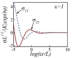 We have already noted that the stress
fields are oscillatory near the crack tip.
The stress distributions are plotted on the right as a function of .
Note that the results are shown for an unphysically large value of - for practical values the oscillations are so
slow it is hard to see them.
We have already noted that the stress
fields are oscillatory near the crack tip.
The stress distributions are plotted on the right as a function of .
Note that the results are shown for an unphysically large value of - for practical values the oscillations are so
slow it is hard to see them.
Both normal and
shear stresses oscillate with increasing frequency as the crack tip is
approached. As a result, it is difficult
to unambiguously separate the loading into normal and shear components an opening stress induces just as much shear
near the crack tip as does shear loading, and vice-versa.
Even more
disturbingly, the crack opening displacements show the same oscillatory
character. This means that the solution predicts that the crack faces overlap
near the crack tip, which is clearly unphysical.
It is possible
to find a solution that corrects for the overlapping crack faces (Comninou, 1977). This solution predicts that the crack faces
touch just behind the crack tip for all combinations of remote load. There is a square root singularity in shear
stress at the crack tip (so it’s strictly always loaded in mode II). The zone of contact is extremely small,
however typically of the order of a few nanometers for
most practical crack sizes and materials, and probably much smaller than the
process zone.
The standard
procedure in LEIFM (linear elastic interfacial fracture mechanics) is to ignore
the overlap between crack faces, and accept the asymptotic field described in
the beginning of this sub-section as characterizing the stress and strain
fields for an interface crack. The oscillatory
singularity is, after all, no less physical than a square root
singularity. The asymptotic field is
expected to represent actual stress and strain fields in an annular region,
which is small compared with specimen geometry, and large compared with the
process zone.
9.6.2 Phenomenological theory of
interface fracture
 Phenomenological fracture mechanics for interfaces
is based on the same reasoning that is used in fracture mechanics of
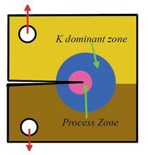
homogeneous solids. We anticipate three
distinct regions in a plastically deforming specimen containing a crack, as
shown in the figure These are
Phenomenological fracture mechanics for interfaces
is based on the same reasoning that is used in fracture mechanics of
homogeneous solids. We anticipate three
distinct regions in a plastically deforming specimen containing a crack, as
shown in the figure These are
1. A process zone near the crack tip, with
finite deformations and extensive material damge, where the asymptotic field is
not accurate;
2. A K dominant zone, outside the process zone,
but small compared with specimen dimensions, where the asymptotic linear
elastic field accurately describes the deformation;
3. The remainder, where stress and strain
fields are controlled by specimen geometry and loading.
Material failure (crack growth or fatigue) is a consequence of the
failure mechanisms in the process zone. As
usual, we do not attempt to model the failure process in detail, and instead
assume that the fields in the process zone are controlled by the fields in the
region of K dominance. In interface
fracture, we use the stress state at the reference length L ahead of the crack tip to characterize the loading experienced by
the process zone. As we have seen, this
stress is characterized by the energy release rate G (or alternatively the stress intensity magnitude ), together with the phase angle .
Fracture Criterion The critical condition for
an interface crack to propagate is therefore given by a fracture criterion of
the form
where is the fracture toughness of the interface and
is the phase angle, defined using some
appropriate choice of length L.
The fracture toughness is a function of phase angle, just as the
fracture toughness of a homogeneous solid subjected to mixed mode loading is a
function of .
 The fracture resistance of the
interface must be measured experimentally. Several specimens are available for this
purpose. Examples include sandwich
specimens (e.g. Leichti & Knauss, 1982; see also Suo & Hutchinson 1989)
and 4 point bend specimens (e.g. Charalambides et al, 1990). Experiments show that increases rapidly with phase angle: the
typical variation of fracture toughness with phase angle is sketched in the
figure. In fact, many
experimental data seem to be fit by .
The fracture resistance of the
interface must be measured experimentally. Several specimens are available for this
purpose. Examples include sandwich
specimens (e.g. Leichti & Knauss, 1982; see also Suo & Hutchinson 1989)
and 4 point bend specimens (e.g. Charalambides et al, 1990). Experiments show that increases rapidly with phase angle: the
typical variation of fracture toughness with phase angle is sketched in the
figure. In fact, many
experimental data seem to be fit by .
To apply LEIFM,
then, it is necessary (i) to measure the fracture resistance of the interface
as a function of phase angle; (ii) calculate energy release rate and phase
angle for the interface crack in the structure or component of interest, and
(iii) apply the fracture criterion to assess the load bearing capacity of the
component.
9.6.3 Stress
intensity factors for some interface cracks
The solutions to interface crack problems are most conveniently
expressed in terms of the stress intensity factors , because
these are linear in stress and can therefore be superposed. Stress intensity factors have been computed for
many standard specimen geometries (usually using a numerical technique). A few examples are shown below.

The point force solutions can be used to calculate stress intensity
factors for interface cracks that are subjected to nonuniform stress fields,
following the procedure given in Section 9.3.3.
The energy release rate and phase angle can be calculated using the
formulas given in the preceding section.
For example, for the slit crack with length 2a subjected to uniform stress far from the crack, the energy
release rate and phase angle are
Note that, for a fixed value of L, the phase angle depends on
the size of the crack. This is a
general feature of interface cracks: the mode mixity depends on specimen
size. However, the value of for most material pairs is very small, so the
variation with specimen size is very weak.
9.6.4 Crack Path Selection
An interface
crack can either propagate along the interface, or deflect into one of the two
materials adjacent to the interface, as shown below. In addition, a crack approaching transverse
to an interface may be deflected along it this is a mechanism for trapping cracks in
composite materials. It can be very
important to predict the path that an interface crack will choose.

A rather
involved linear elastic fracture mechanics calculation is usually used for this
purpose. Although the analysis is challenging, its predictions are simple. A
crack approaching perpendicular to an interface (as shown on the left above)
will deflect along the interface as long as
where is the interface toughness for a phase angle
of 90 degrees, and is the fracture toughness of the material on
the far side of the interface. If this
condition is satisfied, the crack remains trapped in the interface and will not
kink out of it. In practice, this
prediction is reliable only if the specimen geometry and materials satisfy the
conditions necessary for linear elastic fracture mechanics to be a good
approximation. This means that the
materials and interface need to have a low fracture toughness and high yield
stress, so that any plastic zone at the crack tip is very small.
