|
Problems
for Chapter 9
Modeling
Material Failure
9.3. Modeling
Failure by Crack Growth - Linear Elastic Fracture Mechanics
9.3.1.
Using the
equations for the crack tip fields find an expression for the maximum shear
stress distribution around the tip of a plane-strain Mode I crack. Hence, plot approximate contours of
successive yield zones
9.3.2.
Briefly
describe the way in which the concept of stress intensity factor can be used
as a fracture criterion.
9.3.3.
A welded plate
with fracture toughness  contains a residual stress distribution contains a residual stress distribution
along the line of the weld. A crack with length 2a lies on the weld line. The solid is subjected to a uniaxial
tensile stress . Find an expression for the critical value
of that will cause the weld to fracture, in
terms of ,
and a.
9.3.4.
Hard,
polycrystalline materials such as ceramics often contain a distribution of
inter-granular residual stress. The
objective of this problem is to estimate the influence of this stress
distribution on crack propagation through the material. Assume that
·
The solid has
mode I fracture toughness
·
As a rough
estimate, the residual stress distribution can be idealized as ,
where L is of the order of the
grain size of the solid and is the magnitude of the stress.
·
A long (semi-infinite)
crack propagates through the solid at some time t,the crack tip is located at
·
The solid is
subjected to a remote stress, which induces a mode I stress intensity factor at the crack tip
9.3.4.1.
If the solid is
free of residual stress, what value of that causes fracture.
9.3.4.2.
Calculate the
stress intensity factor induced by the residual stress distribution, as a
function of c.
9.3.4.3.
What value of is necessary to cause crack propagation
through the residual stress field?
What is the maximum value of ,
and for what crack tip position c does
it occur?
9.3.5.
A dislocation,
with burgers vector and line direction lies a distance d ahead of a semi-infinite crack.
Calculate the crack tip stress intensity factors.
9.3.6.
The figure
shows a simple model that is used to estimate the size of the plastic zone at
a crack tip. The crack, with length 2a,
together with the plastic zones with length ,
are considered together to be a crack with length . The solid is loaded by uniform stress at infinity.
The region with length near each crack tip is subjected to traction
acting to close the crack. Using the solutions in Section 9.3.3, calculate
an expression for the Mode I crack tip stress intensity factor. Show that
if
9.3.7.
Suppose that an
ASTM compact tension specimen is used to measure the fracture toughness of a
steel. The specimen has dimensions and mm.
The crack length was mm, and the fracture load was 15kN.
9.3.7.1.
Calculate the
fracture toughness of the steel.
9.3.7.2.
If the steel
has yield stress 800MPa, was this a valid measurement?
9.3.8.
Find
expressions for the Mode I and II stress intensity factors for the angled
crack shown. If ,
what is the initial direction of crack propagation? Confirm your prediction experimentally,
using a center-cracked specimen of paper.
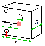
9.3.9.
A large solid
contains a crack with initial length . The solid has plane-strain fracture
toughness , and under cyclic loading the crack growth
rate obeys Paris law
9.3.9.1.
Suppose that
the material is subjected to a cyclic uniaxial stress with amplitude and mean stress (so the stress varies between 0 and 2 ).
Calculate the critical crack length that will cause fracture, in terms
of and
9.3.9.2.
Calculate an expression
for the number of cycles of loading that are necessary to cause a crack to
grow from an initial length to fracture under the loading described in
7.1
9.3.9.3.
Show that the
number of cycles to failure can be expressed in the form of Basquin’s law
(discussed in Section 9.2.7) as ,
where b and D are constants. Give
expressions for b and D in terms of the initial crack
length, the fracture toughness, and the material properties in
Paris law
|