9.4 Energy
methods in fracture mechanics
Energy methods provide additional insight into fracture, and also
provide a foundation for a range of analytical and numerical methods in
fracture mechanics. In this section, we
outline some of the most important results.
9.4.1
Definition of crack tip energy release rate for cracks in linear elastic solids
The crack tip energy release rate quantifies the rate of change of the
potential energy of a cracked elastic solid as the crack grows.
 To make
this precise, consider an ideally elastic solid, subjected to some loading
(applied tractions, displacements, or body forces). Suppose the solid contains a crack (the
figure shows a circular crack with
radius a as a representative
example). Define the potential
energy of the solid in the usual way (Sect 5.6.1) as
To make
this precise, consider an ideally elastic solid, subjected to some loading
(applied tractions, displacements, or body forces). Suppose the solid contains a crack (the
figure shows a circular crack with
radius a as a representative
example). Define the potential
energy of the solid in the usual way (Sect 5.6.1) as
Suppose the crack increases in size, so that the crack advances a
distance with loading kept fixed, where s measures position around the crack
front. The principle of minimum potential energy (sect 5.6.2) shows that , since
the displacement field associated with is a kinematically admissible field for the
solid with a longer crack. The energy
release rate around the crack front is defined so that
Energy
release rate has units of (energy per unit area).
For the special case of a 2D slit crack with length a, the energy release rate is
where is now the potential energy per unit
out-of-plane distance.
9.4.2
Energy release rate as a fracture criterion
Phenomenological fracture (or fatigue) criteria can be based on energy
release rate arguments as an alternative to the K based fracture
criteria discussed earlier.
The argument is as follows.
Regardless of the actual mechanisms involved, crack propagation involves
dissipation (or conversion) of energy. A
small amount of energy is required to create two new free surfaces (twice the
surface energy per unit area of crack advance, to be precise). In addition, there may be a complex process
zone at the crack tip, where the material is plastically deformed; voids may be
nucleated; there may be chemical reactions; and generally all hell breaks
loose. All these processes involve
dissipation of energy. We postulate,
however, that the process zone remains self-similar during crack growth. If this is the case, energy will be
dissipated at a constant rate during crack growth. The crack can only grow if the rate of change
of potential energy is sufficient to provide this energy.
This
leads to a fracture criterion of the form
for crack growth, where is a property of the material. Unfortunately is often referred to as the fracture toughness
of a solid, just like defined earlier. It is usually obvious from dimensional
considerations which one is being used, but its an annoying source of
confusion.
9.4.3
Relation between energy release rate and stress intensity factor
The energy release rate G is closely related to the stress
intensity factors defined in Sect 9.3. Specifically,
for an isotropic, linear elastic solid with Young’s modulus and Poisson’s ratio the energy release rate is related to stress
intensity factors by
HEALTH WARNING: The result relating G to and is valid only for plane strain deformation at
the crack tip.
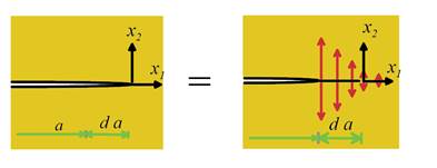
Derivation A neat argument proposed by Irwin
provides the connection.
A crack of length a can be regarded as a crack with which is being pinched closed by an
appropriate distribution of traction acting on the crack faces between and . The crack can be made to propagate by
applying an equal and opposite distribution of tractions that free the crack
faces from stress, as shown below.
We can therefore calculate the
change in potential energy as the crack propagates by distance by computing the work done as these tractions
are progressively applied to the crack. To this end, note that
1. The tractions that pinch the
crack tip closed can be calculated from the asymptotic crack tip field (Sect 9.3.1)
(equal and opposite tractions must act on the
lower crack face).
2. As the crack is allowed to open,
the upper crack face displaces by
where we have assumed plane strain
deformation.
3. The total work done as the
tractions are relaxed quasi-statically to zero is
(the
work done by tractions acting on the upper crack face per unit length is , and
there are two crack faces).
4. Evaluating the integrals gives
The same
result can be obtained by applying crack tip energy flux integrals, to be
discussed below.
9.4.4
Relation between energy release rate and compliance
Energy release rate is related to the compliance of a structure or
specimen, as follows. Consider the
compact tension specimen shown below.

Suppose that the specimen is subjected to a
load P, which causes the point of application of the load to displace by
a distance in a direction parallel to the load. The
compliance of the specimen is defined as
As the crack grows, the compliance of the specimen always increases, so
C is a function of crack length. The energy release rate is related to
compliance C by
This formula applies to any structure or component, not just to compact
tension specimens. The formula is useful
for two reasons:
1. It can be used to measure energy
release rate in an experiment. All you
need to do is to measure the crack length as it grows, and at the same time
measure the compliance of your specimen.
2. It can be used to calculate
stress intensity factors, as outlined in the next section.
Derivation: This result can be derived by calculating the
change in energy of the system as the crack grows. Note that
1. The load P induces a total strain energy in the specimen. To see this, note that the the solid is
elastic and so behaves like a linear spring this is just the formula for the energy in a
spring.
2. Now, suppose that the crack
extends by a distance . During crack growth, the load increases to and displaces to . In addition, the strain energy changes to , while
the compliance increases to .
3. The energy released during crack
advance is equal to the decrease in potential energy of the system, so that
4. Note that
5. Substituting these results into
the expression in step (3) and simplifying shows that
The
energy release rate therefore is related to compliance by
9.4.5 Calculating stress intensity
factors using compliance
 The
relation between compliance and energy release rate can be used to determine energy
release rates, and sometimes also stress intensity factors, for structures
whose rate of change of compliance with crack length can be easily
determined. One example is the cantilever
beam specimen shown on the right. The
mode I stress intensity factor for this specimen can be derived as
The
relation between compliance and energy release rate can be used to determine energy
release rates, and sometimes also stress intensity factors, for structures
whose rate of change of compliance with crack length can be easily
determined. One example is the cantilever
beam specimen shown on the right. The
mode I stress intensity factor for this specimen can be derived as
Derivation This result is derived by first
calculating the compliance of the solid; then using the formula to deduce the
energy release rate, and finally using the relationship between stress
intensity factor and energy release rate.
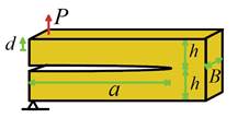
To proceed,
1.  Note that
the deflection d of the loaded point can be calculated by visualizing
the specimen as two cantilever beams, length a, width B and
height h, clamped on their right hand end and subjected to a load P
at their left hand ends as shown on the right. From elementary beam theory, the deflection is
Note that
the deflection d of the loaded point can be calculated by visualizing
the specimen as two cantilever beams, length a, width B and
height h, clamped on their right hand end and subjected to a load P
at their left hand ends as shown on the right. From elementary beam theory, the deflection is
where
E is the Young’s modulus of the specimen.
2. The compliance follows as
3. The energy release rate formula in
Sect 9.4.4 gives
4. By symmetry, the crack must be
loaded in pure mode I. We can therefore
deduce the stress intensity factor using the relation
9.4.6 Integral expressions for energy
flux to a crack tip
In this section
we outline a way to compute the energy release rate for a crack, which applies
not only to linear elastic solids under quasi-static loading conditions, but is
completely independent of the constitutive response of the solid, and also applies
under dynamic loading (it is restricted to small strains, however). The approach will be to find an expression
for the flux of energy through a cylindrical surface enclosing the crack tip, which moves with the
crack. We will get the energy release
rate by shrinking the surface down onto the crack tip.
Energy flux
across a surface in a solid: We first derive a formula that can be used to calculate the
flux of kinetic and potential energy across a surface in a deformable
solid. To this end,
·  Consider an arbitrary surface S, which encloses some volume V
in a solid, as shown in the figure. The surface
need not necessarily be a material surface it could move with respect to the solid. We will denote the velocity of S (with respect to a fixed origin) by
Consider an arbitrary surface S, which encloses some volume V
in a solid, as shown in the figure. The surface
need not necessarily be a material surface it could move with respect to the solid. We will denote the velocity of S (with respect to a fixed origin) by
· Assume that the solid is free of body
forces, for simplicity.
· Let denote the displacement, (infinitesimal)
strain and stress field in the solid, and let denote the velocity of a material point with respect
to a fixed origin.
· Let denote the kinetic energy of a material
particle in the solid
· Let denote the rate of work done by stresses at a
point in the solid
· Define the rate of change of
mechanical energy density at an arbitrary point in the solid as , and let
· Denote the total energy within V as
· Define the work flux vector as
The energy flux
across S can be calculated in terms
of these quantities as follows:
The right hand side of this
expression denotes the energy flux across the surface; the left hand side is
the rate of change of the total energy within V. The two are equal by
energy conservation, as shown below.
Derivation:
1. Begin by showing that the
energy flux vector and the rate of change of mechanical energy density are
related by
To see this, note that
where we have used the
linear and angular momentum balance equations .
2. Now, integrate both sides of this
equation over the volume V and apply the divergence theorem to see that
3. Next note that the total rate of
change of within the volume V bounded by S can be
expressed as
Here, the first term on
the right represents the rate of change due to the time derivative of within V,
while the second term represents the flux of energy crossing S as the surface moves with velocity .
4. Combining (2) and (3) shows that
The term on the right
hand side clearly represents the total rate of change of mechanical energy in V. Consequently, the term on the left hand side
must represent the mechanical energy flux across .
This is the result we need.
 Energy flux to a crack tip. We can use the energy flux integral
to obtain an expression for the energy flux to a crack tip. Suppose the crack tip runs with steady speed v
in the direction.
Let denote a cylindrical surface enclosing the
crack tip, which moves with the crack tip, as shown in the figure. The energy flux through follows as
Energy flux to a crack tip. We can use the energy flux integral
to obtain an expression for the energy flux to a crack tip. Suppose the crack tip runs with steady speed v
in the direction.
Let denote a cylindrical surface enclosing the
crack tip, which moves with the crack tip, as shown in the figure. The energy flux through follows as
where
is the net work
done on the solid per unit volume by stresses, and is the kinetic energy density. The energy flux
to the crack tip follows by taking the limit as shrinks down onto the crack tip.
Contour
integral formula for energy release rate. To obtain an expression for the energy release rate,
assume that the crack tip fields remain self-similar (i.e. an observer
traveling with the crack tip sees a fixed state of strain and stress). In addition, assume that the crack front is
straight, and has length L in direction perpendicular to the plane of
the figure. Under these conditions , and .
Consequently
where C
is a contour enclosing the crack tip. (Equivalent results can be derived for
general 3D cracks, but these details are omitted here).
This result is valid for any material response (including plastic
materials), and applies to both static and dynamic conditions.
9.4.7 Rice’s J integral
The result derived in the preceding section becomes particularly useful
if we make two further assumptions:
1. Loading is quasi-static;
2. The material is elastic.
In this case T=0 and is simply the strain energy density in the
solid - e.g. for a linear elastic solid
with no thermal stress,
The
expression for energy flux through a surface surrounding the crack tip reduces
to
This is
the famous J integral. It has the following properties:
1. The crack tip energy integral is path
independent, as long as the material enclosed by the contour is
homogeneous. There is no need then to
shrink the contour down onto the crack tip we get the same answer for any contour
that encloses the crack tip.
2. J=G for an
elastic solid - so the contour integral gives an elegant way to calculate the
crack tip energy release rate.
 Path independence of J: To show this, we first show that
if the J integral is evaluated around
any closed contour that does not
enclose the crack tip, it is zero. To
see this, apply the divergence theorem
Path independence of J: To show this, we first show that
if the J integral is evaluated around
any closed contour that does not
enclose the crack tip, it is zero. To
see this, apply the divergence theorem
where A is the area enclosed by , as
shown in the figure. To see that the area
integral on the right hand side is zero, note that
where we
have used the equilibrium equation .
 Now,
evaluate the integral around the closed contour shown in the figure. Note that the integrand vanishes on and so that
Now,
evaluate the integral around the closed contour shown in the figure. Note that the integrand vanishes on and so that
Now reverse the direction of
integration around (note that m = -n) to get
showing that the integral is equal
for any two contours that start and end on the two crack faces.
9.4.8 Calculating energy release
rates using the J integral
The J
integral has many applications. In some
cases it can be used to compute energy release rates. For example, consider the problem illustrated
below. A cracked linear elastic cracked sheet is
clamped between rigid boundaries. The
bottom boundary is held fixed; the top is displaced vertically by a distance .
Calculate the energy release rate for the crack.
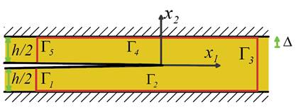
For this case G=J,
and we can easily evaluate the J integral around the contour shown in the
figure. To do so, note that
1. Far behind the crack tip ( ) the solid is stress free. The J
integral vanishes on and
2. The displacement field is constant on
so that there.
In addition on and .
The J integral vanishes on and , therefore.
3. Far ahead of the crack tip , the displacement, stress and strain
energy density can easily be calculated as
The contribution to the J
integral from follows as
The energy release rate is therefore
Symmetry
conditions show that the crack must be loaded in pure mode I, so the stress
intensity factor can also be computed.
